Imagine you are sourcing a precision shaft that carries a bearing on one end and slides through a hydraulic seal along its length. The drawing shows a circularity tolerance of 0.01 mm on the bearing journal and a cylindricity tolerance of 0.02 mm on the seal surface. The two symbols look similar, yet they control very different kinds of error. Misreading them is expensive: circularity will not catch a taper that makes the shaft bind in the bore, while cylindricity adds inspection cost that may not be justified on a short seal seat. This article explains what each callout controls, how their tolerance zones differ, how they are measured, and how to choose the right one.
What Is Circularity in GD&T?
Circularity, also called roundness, is a two-dimensional form control defined in ASME Y14.5 and ISO 1101. It limits how far any single cross-section of a cylindrical, conical, or spherical surface can deviate from a perfect circle. The feature control frame shows the circle symbol followed by one tolerance value and no datum reference, because circularity controls form only and does not locate the feature.
The tolerance zone for each cross-section is the area between two concentric circles separated by the tolerance value. The two circles may shift their common center freely; circularity does not constrain where the cross-section sits in space. It only limits the radial gap between the highest and lowest points in that one plane.
Because circularity applies to each cross-section independently, it cannot detect problems along the axis of the part. A shaft that is perfectly round at every measured ring but tapers from one end to the other will pass a circularity callout easily. That limitation is the reason cylindricity exists.
What Is Cylindricity in GD&T?
Cylindricity is the three-dimensional extension of circularity. It controls how closely an entire cylindrical surface conforms to a perfect cylinder, combining roundness, straightness, and taper into a single composite tolerance. The feature control frame carries no datum reference, for the same reason as circularity: the control is purely about form.
The tolerance zone is the volume between two coaxial cylinders whose radii differ by the tolerance value. The common axis of the two cylinders may shift and tilt freely in space. Every point on the entire surface must lie between the two cylinders for the part to pass.
In practical terms, a cylindricity callout requires the part to be round in every plane, straight along its entire length, and free from taper, hourglass, and barrel-shaped errors. This is why it is the form control of choice on hydraulic cylinder bores, piston outer diameters, valve spools, and shafts that must maintain uniform clearance over a long engagement. Stepped shafts used in automotive assemblies are a typical example: the drawing often specifies circularity at bearing seats and cylindricity on sliding sections that pass through seals.
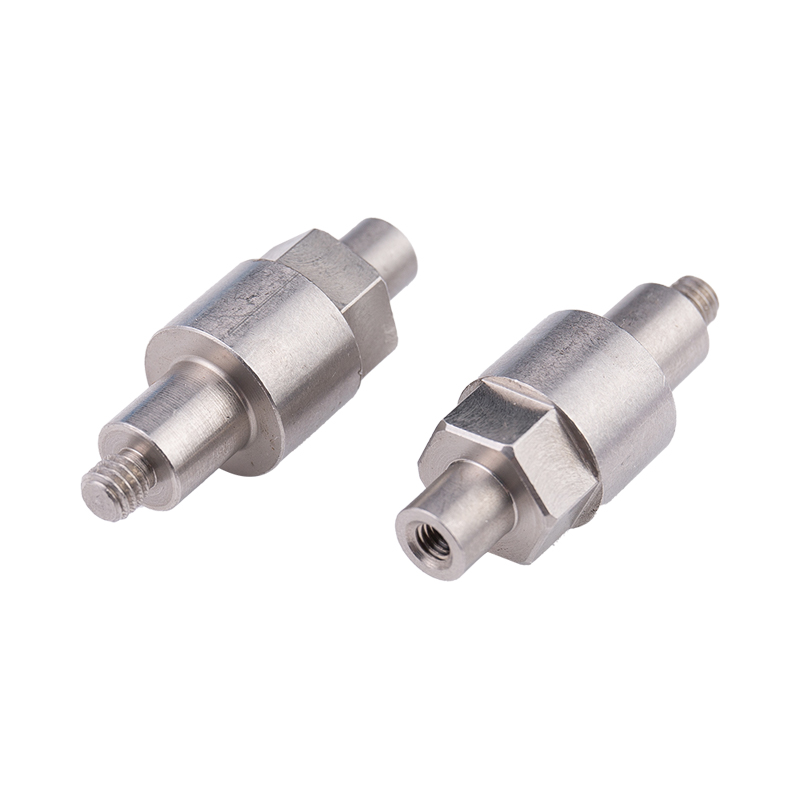 Precision Stepped Shaft Manufacturing for Automotive Sliding Sections Stepped shafts are called out for cylindricity on sliding sections that pass through seals. This maker supports custom stepped shaft machining with precision equipment, making it relevant for comparing suppliers on form control capability. View Product →
 Circularity vs Cylindricity: Key Differences at a Glance
Practical differences between circularity and cylindricity in GD&T. | Aspect | Circularity | Cylindricity |
| Dimensional nature | 2D per cross-section | 3D entire surface |
| Tolerance zone | Annulus between two concentric circles | Volume between two coaxial cylinders |
| What it controls | Roundness in a single plane | Roundness, straightness, and taper |
| Datum required | No | No |
| Measurement approach | One trace per cross-section | Multiple traces or helical scan |
| Relative inspection cost | Lower | Higher |
| Typical applications | O-ring grooves, seal seats, bearing journals | Hydraulic bores, pistons, long mating shafts |
As the table shows, cylindricity is not simply a stricter version of circularity. It controls a different kind of error that circularity cannot see, and it requires a different measurement strategy.
How Circularity and Cylindricity Are Measured
Measuring circularity
Circularity is measured with a roundness measuring instrument or a coordinate measuring machine. The roundness instrument rotates the part on a precision spindle while a probe follows one circular path; the software reports the minimum radial zone that contains the trace. A CMM can achieve the same result by probing points around a single cross-section and fitting the tightest pair of concentric circles.
Measuring cylindricity
Cylindricity demands far more data. The probe must trace multiple cross-sections along the length or follow a helical path, and the software fits the tightest pair of coaxial cylinders around all measured points. The result is strongly affected by how many levels were measured, the spacing between levels, and how precisely the part axis was aligned to the measuring axis.
The cost gap is real. A circularity check on a 50 mm diameter ring can be completed in minutes. A meaningful cylindricity check covering a 200 mm length at five or more levels can take an order of magnitude longer and is often done off-line on dedicated equipment. That is why you should always ask how a cylindricity callout will be verified. Some suppliers report cylindricity values from just two circular traces, which seriously understates the actual form error. A manufacturer with a disciplined approach to dimensional accuracy will document the measurement plan up front, including the instrument, the number of traces, and the spacing between them.
Simple cylindrical parts such as alignment pins and dowel pins are on the other end of the spectrum: a circularity check at the critical seating section is usually enough to protect function, and specifying cylindricity over their short length adds cost without adding value.
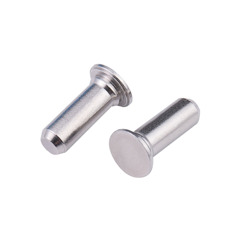 Custom T-Shaped Cylindrical Pins for Part Alignment and Fixing The article notes that simple cylindrical parts often only need circularity at critical seats. T-shaped cylindrical pins from this supplier fit that case, and the page offers custom machining in carbon or stainless steel to match drawing callouts. View Product →
 When to Use Circularity vs Cylindricity
Use circularity when the function depends on roundness in a specific cross-section only
- O-ring grooves and face seal seats
- Bearing journals where the rolling element sits at a defined axial position
- Short cylindrical features whose length is small compared with their diameter
- Spherical seats where only one plane is functional
Use cylindricity when the entire length of the cylindrical feature participates in the function
- Hydraulic cylinder bores and piston skirts
- Pneumatic valve bodies and spool diameters
- Shafts that slide through long bushings or multiple seals
- Press-fit connections that require uniform interference over the full engagement length
When both callouts appear on the same part, the cylindricity tolerance is almost always larger than the circularity tolerance. Controlling a whole surface is harder than controlling one ring, so a larger value is needed to keep the process economic. If you see a drawing with a cylindricity tolerance tighter than the circularity tolerance, challenge it: it may be a drafting error or a sign that the designer does not fully understand the difference.
Steel bushings used in automotive pivot joints illustrate both callouts on one part: circularity on the outer press-fit diameter, and cylindricity on the bore that must guide the pin with uniform clearance.
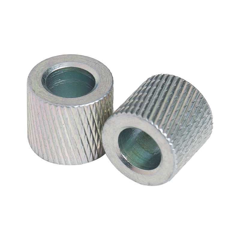 Steel Bushings with Combined Circularity and Cylindricity Control Steel bushings in automotive pivot joints require circularity on the press-fit diameter and cylindricity on the bore. This manufacturer lists steel bushings and processing capabilities, supporting parts that need both form tolerances. View Product →
 Practical Guidance for Sourcing Parts with Form Tolerances
When you request a quotation for machined parts with circularity or cylindricity callouts, focus on three things.
First, confirm which surface each callout controls. A quick review with the supplier before quoting can catch parts that are over-constrained or under-constrained, both of which cost money.
Second, agree on the measurement method. The drawing should state, or the supplier should propose, how many cross-sections will be measured for cylindricity and what instrument will be used. A written inspection plan avoids disputes at first article inspection.
Third, match the tolerance to the real process. Circularity values around 0.01 mm are routinely held in precision turning. Cylindricity values below 0.01 mm on long parts almost always require cylindrical grinding or lapping, with a direct impact on lead time and price. Knowing this before you place the order helps you set realistic expectations and compare quotations fairly.
Working with a supplier that understands both the drawing intent and the measurement burden is part of smart sourcing. A precision hardware manufacturer with experience across automotive, mechanical, and industrial components will help you review form tolerances before tooling starts and will give you an honest answer about whether circularity is enough or cylindricity is truly needed.